RoboArm Controller, part I: Intro and architecture.
by Enrique Llerena Dominguez
Learning Machine Learning Series
This is the first post of a series where I want to describe my journey learning machine learning, a topic I am passionate about.
RoboArm Controller, part I: Intro and Architecture
TL;DR
- The RoboArm Controller enables a user to control a simulated robotic arm with the position of their hands.
- Check out the code at the Github repo: ellerenad/RoboArmController
- Demo
- The following technologies were used: Java, Python, C++, Tensorflow, Deeplearning4j, Spring, JUnit, Gazebo, plus other tools.
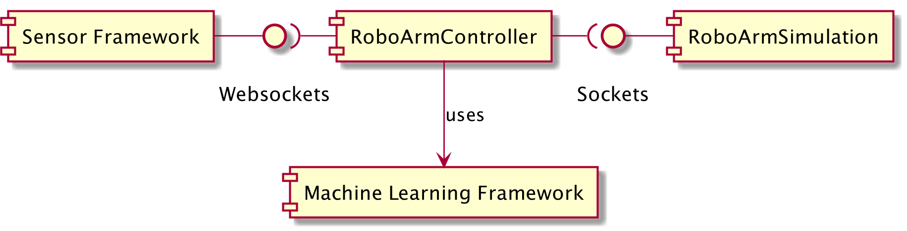
- The RoboArm Controller has 3 main components: a simulated robotic arm, a data transformation application, and the hands’ sensor.
- The machine learning part is on the data transformation: classify the position of the hands to get a movement instruction.
- The RoboArm Controller covers the machine learning cycle: Gather the data, prepare the data, choose a model, train the model, tune the hyperparameters, test the model, export the model, import the model into a “production” system, and use it to make predictions.
- The project was presented at the Java Forum Stuttgart 2019 and the EclipseCon Europe 2019 (video/slides)
- The RoboArm Controller is a hobby project I developed to practice different technologies in a ludic way.
Introduction
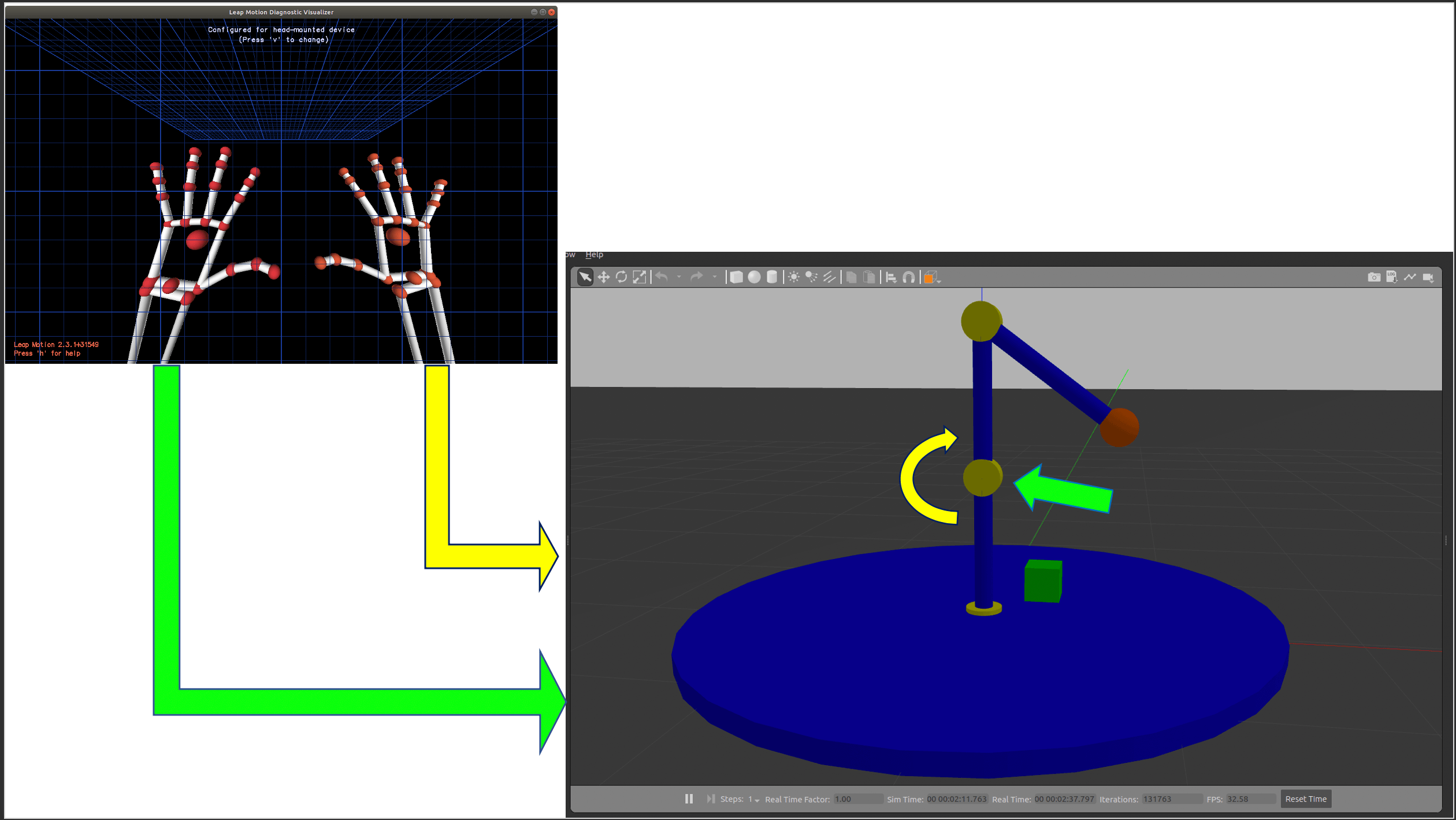
The RoboArm Controller allows controlling a simulated robotic arm with the position of the hands of a person.
In this implementation, the position on the left hand of the person is used to indicate which servo to move, and the position
of the right hand is used to determine whether the change of the current position of the servo needs to negative or positive.
The simulated robotic arm has 3 degrees of freedom, i.e. 3 servos.
From a machine learning perspective, it can be seen as a classification problem: There is a bunch of coordinates, representing
the position of a hand, and the goal is to transform them into an instruction, so that:
Instruction = map(classify(hand)), where an example of an Instruction is Move the servo number 1 applying a positive change.
This fits the learning goals (mentioned on the afterword) because:
- The RoboArm Controller is a data stream, where the data originates on the sensor, is transformed, and eventually it “moves” the simulator.
- The RoboArm Controller can be controlled with a machine learning part because the transformation of the data is a classification problem, where the positions of the hand have a label, which itself can be mapped to an instruction.
- The RoboArm Controller enables the practice of the machine learning framework because it is an end to end machine learning system, executing the following steps: Gather the data, prepare the data, choose a model, train the model, tune the hyperparameters, test the model, export the model, import the model into a “production” system, and use it to make predictions.
Architecture
This is a data stream: the data is originated on the hands’ sensor, then it is read by the data transformation application, where it is transformed from a set of positions to either a data set or to a movement instruction, and on the latter case sent to the robotic arm, where the instruction is interpreted and applied to the simulation.
It has 3 main components:
- A hands sensor.
- A data transformer application.
- A simulated robotic arm.
Note: I don’t consider the Machine Learning module as a component, from my perspective it is more a tool used by a component or even an implementation detail. I show it here because it is a goal on the project: learn a machine learning framework.
If you want to see more diagrams related to the architecture of this project, you can find them at the Architecture folder of the GitHub repo
Brief Description of the Components
This is just an overview of each of the main components used for the project. If these series get enough traction, I will write a post describing each one of them
Hands’ Sensor
This is the origin of the data, where the position of the hands is sensed. Used the Leap Motion sensor. It has a framework to communicate with different languages, but the way I got to talk with it was through a WebSocket. It provides coordinates for a set of points related to the hands, e.g. the tips of the fingers, the center of the hand, and so on.
- Technologies used: Leap Motion.
- Interfaces: Websocket.
- Input: The hands.
- Output: Position of different parts of the hands, sent to the data transformer application.
The Data Transformer Application
This is the place to find the main domain logic. It is a Java/Spring Boot application, where the hands’ position data is transformed into movement instructions for the simulated robotic arm. It has an internal onion architecture, where I applied my knowledge of domain-driven design. It has 2 different execution states:
- Training mode: Generation of the data set + training of the machine learning model (when the used framework allows it, details below). It takes the positions read from the hands’ sensor, process them, creates a data set, and tries to trigger the training for the machine learning model.
- Control mode: Transformation of the hands’ positions into movement instructions. It takes the positions read from the hands’ sensor, process them, and feeds this data to the machine learning framework for classification, then interprets this data, transforms it to an instruction, and sends it to the robotic arm via TCP sockets.
Two machine learning frameworks are supported:
- Tensorflow (v1).- This framework does not allow the training with java, hence the training needs to be done with a separate python script, it is provided in the form of a Jupyter notebook.
- Deeplearning4j.- This framework provides support to train a model with java, so the model is generated.
The execution states and the used machine learning framework are controlled through Spring profiles.
- Technologies used: Java + Spring, jUnit, maven, TensorFlow, deepelearning4j.
- Interfaces: WebSocket, TCP Socket.
- Input: Position of different parts of the hands.
- Output: Instructions for the robotic arm. e.g. ´1 -5´, meaning “move ´5´ negative degrees the servo with id ´1´”
Simulated Robotic Arm
It is a -rather simple- simulation of a robotic arm, done in Gazebo, with 3 degrees of freedom. It is controlled by a C++ plugin.
This plugin receives instructions from the exterior on a TCP port, with the format <servoId delta>, so the instruction 1 5
would move the servoId: 1 5 positive degrees.
- Technologies used: Gazebo, C++.
- Interfaces: TCP Socket.
- Input: Instructions from the data transformer application.
- Output: Visualization of the Robot Arm. It could also return the position of the servos.
Conclusion
We saw an overview of the motivation behind the RoboArm controller project, the architecture it has, and a brief description of its components. If this series gets traction, I will write more posts about it, the next would be the data transformer application, as it is the component I find the most interesting. If you find this interesting, reach me on twitter!
If you want to see more about this, check the following links:
Afterword: How This Project Started
Some time ago, after having done the MOOC “Machine Learning for Musicians and Artists” at kadenze, I was eager to apply my knowledge, so I started to look for a project to get the hands dirty with. It was not an easy task, as a parent I don’t have a lot of time for a side project, maybe just a couple of hours per week.
I was looking for the following characteristics for a project:
- Make me feel passionate about it.
- Be an end to end Machine Learning system.
- Let me experiment with different technologies in a ludic way.
Learning goals:
- A Machine Learning Framework: Tensorflow, deeplearning4j.
- Apache Kafka.
- Gazebo.
The idea came connecting the dots of previous stuff I had done and seen:
- A simulated robotic arm I made for my masters’ thesis.
- The Leap Motion controller, that I got to know at the above-mentioned MOC from Kadenze.
I have not yet integrated Apache Kafka, let’s see what the future says :)
Evolution of the Project
The strategy to achieve the goals were:
- Do a Minimum Viable Product.
- Do small iterations to create small pieces with clearly testable deltas.
- Tackle the riskiest things first.
Major milestones:
- Get data from the sensor.
- Model the simulated robotic arm, control it and communicate it with the exterior.
- Transform sensor data into movements: Process data and communicate all the components.
I made an initial prototype with partial failures where I learned some nice stuff, but I’ll leave the evolution to another post.
Subscribe via RSS